The larger we make a memory system, the slower and more expensive that it is. So we can make small fast memories, and large slow memories, but cannot make one memory that is as large as we want and as fast as we want.
In order to address this, we instead have a hierarchy of memory, with some small fast memories and some large slow ones.
The following table gives common levels of the memory hierarchy, along with estimate values of the sizes and times. Exact values depend on the architecture, but these give you an idea:
| Memory | Size | Latency |
| Register File | Tiny (1 Kb) | 1 clock cycle |
| Level 1 Cache | Small (32 Kb) | 2 clock cycles |
| Level 2 Cache | Medium (4 Mb) | 8 clock cycles |
| Main Memory | Large (8 Gb) | 200 clock cycles |
| Hard Drive | Huge (1 Tb) | 10,000,000 clock cycles |
The goal then is to keep the things we use the most in the caches. Ideally, most of the time we access memory we can quickly retrieve values from the cache and only rarely need to go all the way to main memory.
If programs accessed memory in a uniform, random way caches would not work. If we read values scattered across the range of possible addresses with no patterns, then we would be unlikely to find anything in the cache.
But most programs exhibit the principles of locality which summarize patterns in the way common programs make memory accesses. There are two principles of locality:
Temporal locality:
This says that programs which access a memory location once are likely to access it again soon. Think about the code you write. When you access a variable, it's quite likely your program will access that same variable again soon. Also, our program code is stored in memory as well. Any program with a loop exhibits temporal locality since we are reading the instructions in the loop over and over.
Spatial locality:
This says that programs which access a memory address are likely to access nearby addresses soon. There are many examples of spatial locality in the code we write:
Caches exploit the principles of locality to make it so accessing the same memory address again, or a nearby address, is likely to result in the value being present in the cache.
We begin by dividing memory into cache lines, which are typically 64 bytes. The cache loads entire lines from main memory and never individual values. This works towards spatial locality since we load multiple words in each cache line.
When we read or write an address, we will begin looking in the cache first. If the value is there, we access it there. This is called a cache hit. If the value is not there, it's a cache miss. Ideally we will have many more hits than misses. Well-designed caches for typical programs achieve hit rates well above 90%.
In designing a cache, we need to solve the following problems:
The simplest cache design is called a direct-mapped one, because each line in memory has exactly one place in the cache that it can be stored in. We decide how many entries the cache will have, and use the lower bits of the address to determine which location in the cache. For now we will assume that the cache stores lines of only one byte each.
In the following diagram, we have a cache of size 4 and so need 2 bits to index the cache. For any memory address, we take the lower 2 bits of the address to decide which cache location it is mapped to:
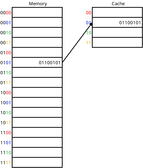
A direct mapped cache
In this scheme, addresses 0, 4, 8, 12, 16, 24, etc. will all be mapped to cache location 0. If any of them are accessed, we will pull them into cache location 0. This answers question 1 above — we now know where to put a line based on its address. For example, address 5 maps onto cache location 1 in the diagram.
But this does not give us an answer to question 2. In the diagram, how do we know that the data in cache line 1 belongs to address 5 vs. address 1, 9, or 13? In order to know this, we also include a tag for each cache line, which is the rest of the memory address that we put here:
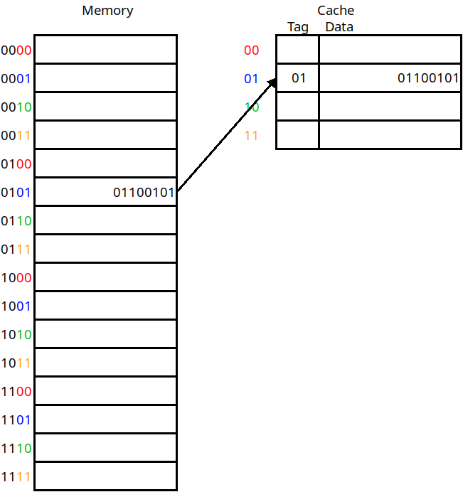
The use of tag bits
This diagram includes the tag column for each line stored in the cache. This includes whatever address bits were not used as the cache address. Now if we want to do a load instruction from memory address 5, we take the lower bits of the address (01) to decide which cache line to check. Then, we need to match the tag against the upper bits of the address to verify that this is the right value. If the tags match, then it's a hit. Otherwise a miss.
There's one more thing we need to store in the cache for each line as well, and that's whether the data for this line is valid at all. When a program is first beginning to execute, the cache will not be full yet and we need to know if the cache lines contain what the tag says it does, or if it's just not been set at all yet. To this end, we include a valid bit for each line as well:
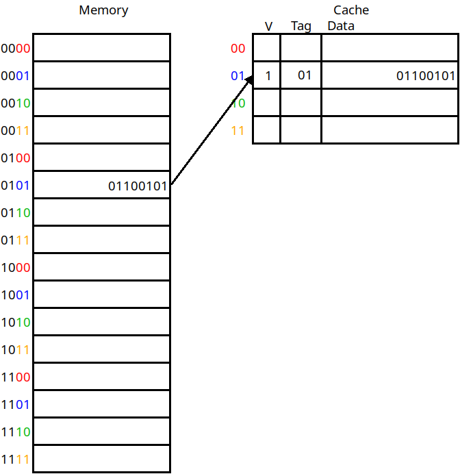
The inclusion of a valid bit
If the valid bit is 1, we know the cache line stores the value of the address indicated by the tag. If it's 0, we know we just have not loaded anything into this cache line yet.
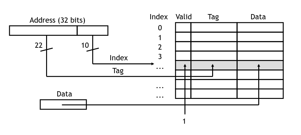
The cache has logic to check if a given address is stored within, and return it if so. In the diagram below, we have 32-bit addresses:
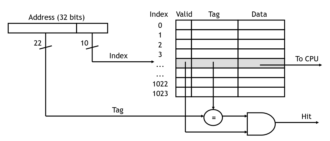
Accessing an element in the cache
Here, the lower 10 bits will be used to index the cache. We will send the data for the cache line back to the CPU along with one bit telling us if it was a hit or not. This is true when the valid bit is on, and when the tag matches the upper bits of the address we are trying to load.
If the hit signal is true, the CPU will take the loaded value and carry on. Otherwise we will need to wait for the value to come from main memory (and be loaded into the cache). The simplest way to handle this is to stall the pipeline until the value is ready. (Higher performance processors will attempt to go out of order, executing other instructions that do not rely on the load value).
When the value does arrive from main memory, we write it into the cache. To do this, we set the data into the cache line indicated by the lower bits of the address, set the tag to the upper bits, and set the valid flag to 1:
Setting an element in the cache
For the direct-mapped cache, there is only one location mapped for each cache line. So there is no decision to make on which data to replace with new data. This is based on the assumption that the more recently accessed data is more likely to be accessed again than whatever was already in there. Locality tells us this is generally true, but there could be situations where we're using multiple addresses that map to the same cache locations. This is called contention and we'll look at a technique to alleviate it a bit later.
First though, we'll look at using cache lines of more than just a single byte. We will do this to take advantage of spatial locality in addition to temporal. This way when we load data into the cache the nearby addresses will be loaded along with it.
A line size of 64 bytes is fairly typical for a real cache, but lets imagine a cache with a line size of 4. We will load 4 bytes into each cache line from memory:
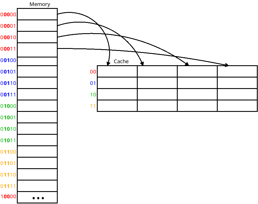
Using a line size of 4
Here we copy from memory into the cache four bytes at a time. If we load any of the bytes within the cache line, we must pull the line containing that byte in. This cache is still direct-mapped in that each line can only go into one location in the cache.
This allows us to provide spatial locality. If we have an array of bytes (such as a string) and load the first byte, the next three will already be in the cache when we need them. With larger line sizes, we have more locality — with a line size of 64 we would be able to pull in 16 int or float variables that are stored contiguously in memory.
Now the addressing is slightly more complicated. The two least significant (rightmost) bits are now the line index which tell us which byte in the cache line this address is. Since this example uses 4 byte cache lines, this is the lower 2 bits. In a 64-bit line cache, we'd use the lowest 6 bytes for this purpose.
The next least significant bits are the block address which tell us which cache location this line will be loaded into. These are the two bolded bits in the addresses in the diagram. Here there are two such bits because our cache contains 4 cache lines. If we had 1,024 cache lines then we would use 10 bits for the block address.
As before the rest of the bits of the address are used as a tag. In the diagram, that would be all but the lowest four bits.
In this scheme, if we have the address 0x4a, what would be the following
values?
Now we will look at the issue of contention. If we have multiple sections of memory fighting for the same block address, our direct-mapped cache will not perform very well. This can be solved by allowing a cache line to be placed into more than just one location in the cache, which is called associativity.
One way we can do this is by making a fully associative cache which is one that permits cache lines to be stored in any of the cache locations. In doing this, there is no block address any longer. Instead we increase the size of the tag to include all of the address except for the line index. Now we must check all of the cache locations to see if the tag matches that of the address we're looking for:
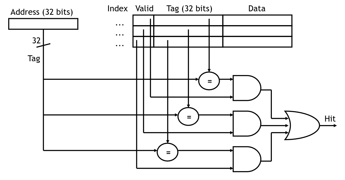
Checking tags in a fully associative cache
In this diagram, we are assuming that each value in the cache is a single byte. If we have a larger line size, then we would use fewer bits for the tag. For instance, if we have 32-bit addresses and the line size is 64 bytes, then the line index is 6 bits and the tag is 26 bits.
The upside of a fully associative cache is that we will not have contention problems. Since any line from memory can be loaded into any location in the cache, we won't have a problem where two lines are fighting for the same place.
The downside is that having all of the circuitry to check the tags increases the size, cost, and energy consumption of the circuit. If the cache contains 1,024 lines, then we need that many 26-bit comparators which is a lot of gates! The direct-mapped cache needs only one comparator because we know where the cache line will be (if it's present).
The trade-off taken by most cache systems is set associativity. In this scheme, we choose a number of blocks in the cache that each line could be in. For example, if we have a cache of size 8, we could use any of the following organizations:
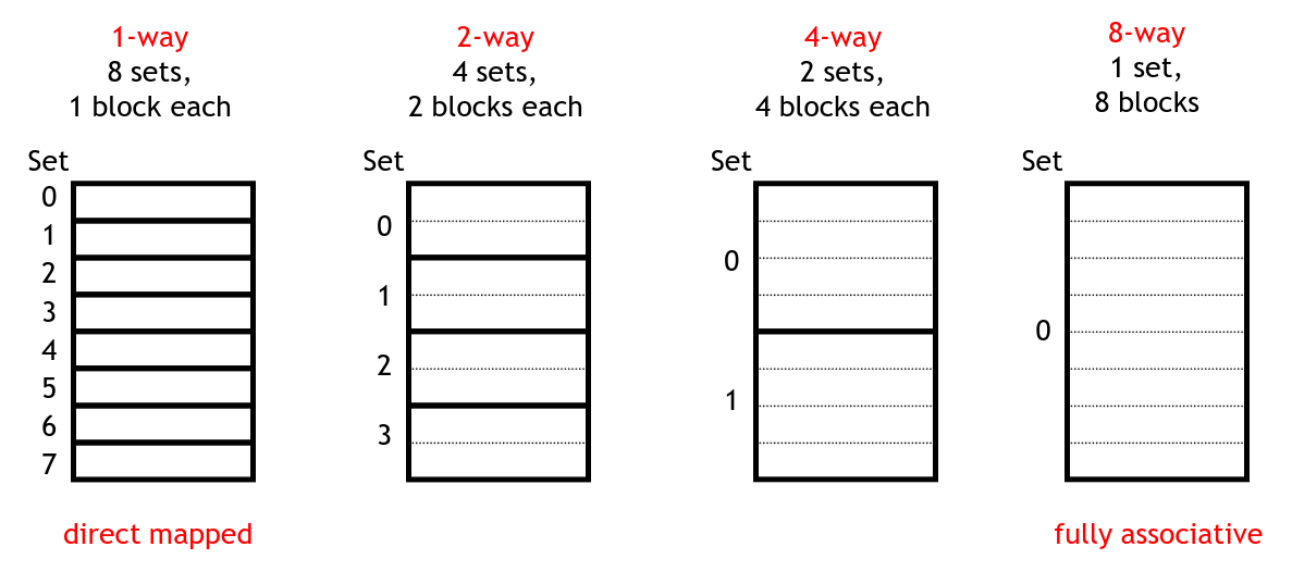
Organizations for a size 8 cache
The leftmost one is simply a direct-mapped cache. The next two organizations show a 2 and 4 way associative cache respectively. On the right is a fully-associative cache in which a line could be loaded into any of the 8 cache blocs.
With set associativity, we aim to avoid most of the downsides of direct-mapping and full associativity. Since there are multiple blocks each line could go in, the odds of having contention problems are much lower. And we only need $N$ tag comparators instead of one for every block in our cache.
With a direct-mapped cache, our block index is the lower $N$ bits of the address where we have a $2^N$ size cache. With a fully-associative cache, there is not block index and we have a larger tag we must check. The logic for a set associative cache is somewhere in between.
For example, let's assume we have the following cache system:
In this system, our address will be broken down like this:
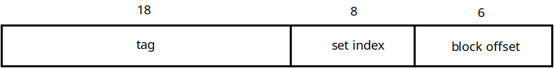
Address Organization for a 4-way cache
The lowest 6 bits are the block offset. This comes from the fact that each line holds 64 bytes. This tells us where in the cache line this specific byte is located.
Next comes the set index, which tells us which of the sets of our cache to look in for this address. This is 8 bits in this example because if we have 1,024 blocks in a 4-way associative cache, then there are $1024 \div 4 = 256$ sets. Since there are 256 sets, we need 8 bits to specify which set this address maps to.
Finally the remaining bits comprise the tag. As before we use these to check that the line in the cache corresponds to the one we are actually looking for.
In this example, when we do a load and check the cache, we will take the set index and then compare the tags for all four lines in that set. If one of them matches (and is valid), then we have a cache hit. If none of them match, we have a cache miss.
Associativity introduces a new problem for us: how do we determine which block to replace when one is loaded in? In a direct-mapped cache this does not come up, because there's only one place each line can go. In an associative cache we have a choice from any cache block in a fully-associative cache to $N$ blocks in an $N$-way associative one.
What we would want to do is replace the line that was accessed the longest time ago. Temporal locality tells us this line is the one that we are least likely to need again in the future. This scheme is called "Least Recently Used" or LRU. The problem is that LRU is relatively expensive to implement. Each cache line will need a counter telling us when it was accessed relative to others. In an 8-way associative cache this would need to be a 3-bit number. On every cache access, we would need to update all of the counters in the set.
Let's say the current state of the counters for lines in a set looks like this:
| Set | Counter |
|---|---|
| 0 | 6 |
| 1 | 2 |
| 2 | 5 |
| 3 | 3 |
| 4 | 0 |
| 5 | 1 |
| 6 | 7 |
| 7 | 4 |
The lower the counter value, the more recently we accessed the cache line. So in this case, if we need to replace one of the lines in this set, it should be the one in block 6, since that one was accessed least recently. Then, we need to set the counter for that line to 0, and then increment all of the other counters. This is why LRU is costly to implement — we need to put in adders for all of the blocks in a set to do the increments.
Instead, we can use a so-called "pseudo-LRU" scheme which approximates true LRU. In one such scheme, we simply store one bit for each block in a set, called the MRU bit. Whenever we access a line in a set, we set this bit to 1. This might look like this:
| Set | MRU |
|---|---|
| 0 | 0 |
| 1 | 1 |
| 2 | 1 |
| 3 | 0 |
| 4 | 0 |
| 5 | 1 |
| 6 | 0 |
| 7 | 1 |
Here, we have accessed blocks 1, 2, 5, and 7 more recently than the others. When it comes time to replace a line, we will thus choose the first one with a 0 MRU bit, setting that ones bit to 1. Eventually all of the MRU bits will be 1, at which time we will set them all back to 0.
This is not true LRU, but is much simpler to implement and will not replace the most used lines most of the time.
Copyright © 2024 Ian Finlayson | Licensed under a Attribution-NonCommercial 4.0 International License.