Complex circuits are not necessarily built from scratch by hardware designers. There are tools which can take truth tables or boolean expressions and construct circuits from them automatically. These tools are also generally able to simplify circuits so that they use fewer logic gates.
In this lab, we will learn how to do this with Logisim.
Logisim is capable of building circuits automatically from a truth table or an expression. To get started, click the "Window" menu, and then "Combinatorial Analysis". This will open a second window for creating a combinatorial circuit.
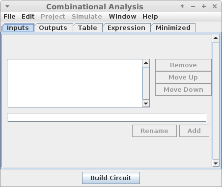
First you must enter the inputs and outputs of the circuit. These will create pins which are labeled with the name you give the input or output.
Here, I created three inputs for a simple multiplexer circuit:
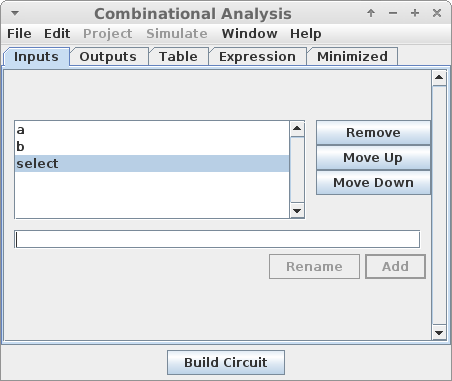
And one output for the circuit:

Next, you have to specify the circuit behavior. There are two ways to do this:
Filling in a Truth Table
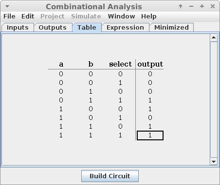
In the "Table" tab, you can fill in the desired values for each output, given each possible input combination. In doing this, you will see that "x" is one of the possible values. Here, x means that we do not care about the value in a particular cell in a table. For example, if we know that one combination of inputs will never arise, we don't need to stipulate the circuit behavior for that case. This can result in simpler circuits than if we specify default values.
Below is a truth table for the multiplexer:
Specifying an Expression
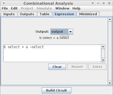
In the "Expression" tab, you can write a boolean expression for each output which also is sufficient to specify the circuit behavior. Note that Logisim uses a space between inputs to mean "AND". It uses the "+" operator to mean "OR", and the "~" operator to mean "NOT".
Below is the expression generated for the multiplexer:
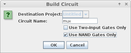
In the "Minimized" tab, you can see a simplified version of the expression which governs your circuit. When you are read, click "Build Circuit" which will generate the gates for you.
In addition to giving the circuit a name, you can specify that the circuit should use only two-input gates, or that the circuit should be built out of NAND gates alone.
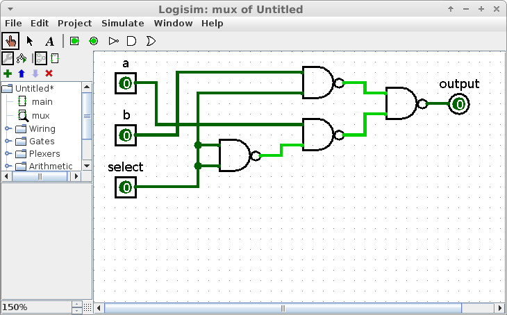
Then, Logisim will display the generated circuit for you. The multiplexer made of NAND gates looks like this:
Large circuits are built out of smaller components in a hierarchical way, just like large programs are built out of smaller functions. This is done for the exact same reasons:
When we create a circuit using the combinatorial analysis tool in Logisim, it automatically makes it a component which can be added into something else. Notice on the left-hand side of the window, Logisim has something called "main". This is our "main" circuit which is similar to the main function in a C program - it is the top-level design which may reference other, smaller components.
When we created the multiplexer above, it creates a component which can be added into the main circuit. Adding it looks like this:
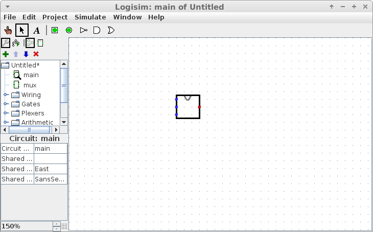
By default, the multiplexer has the three inputs on the left and the output on the right, and is drawn as a rectangle.
To build a complicated circuit, we should look to break it into manageable chunks, just like when writing a complicated program.
For this lab, you will make a circuit which will test if a date is valid or not. For example, the dates "October 31", "February 20" and "April 30" are all valid, but the dates "November 31", "February 30" and "April 31" are not.
To do this, you should create two different circuits using the combinatorial circuit creator:
Month to Max Days
This circuit should take four inputs which represent the month. Month 0 is January, month 1 is February and so on. It should take a fifth input pin which represents whether the year is a leap year or not.
This circuit should have two outputs which together represent the number of days in the month:
| Output | Days in Month |
| 00 | 28 |
| 01 | 29 |
| 10 | 30 |
| 11 | 31 |
Note that these binary numbers are in fact the last two bits of the days. E.g. the last two bits of 28 are 00, the last two bits of 29 are 01, and so on.
The months with numbers 12 through 15 should have 'x' as their output - we won't have them as inputs, so it doesn't matter what the outputs are.
To make this circuit a little less tedious to enter, put in all of the inputs and outputs except for the "leap" one, then fill out the table. Then, add the "leap" input. Logisim will duplicate all of the entries, and you will only need to change February.
Two-Bit Less Than or Equal To
The second circuit you should generate is one capable of comparing two two-bit numbers. The circuit should take four bits as input, representing the two values. The output of the circuit should be 1 whenever the first value is less than or equal to the second value, and 0 otherwise.
You should then build the "main" circuit which has 4 pins for the month, 5 pins for the day, and one pin for the leap year. Wire the month and leap year pins into the "Month to Max Days" circuit.
Wire the output of the "Month to Max Days" circuit, along with the lower two bits of the day into the "Two-Bit Less Than or Equal To" circuit. If that circuit outputs a 1 or if any of the three highest bits of the day counter are 0, then the day is valid. Otherwise, the day is not valid. You should wire this to an LED so that the light turns on whenever the inputs reflect a valid day, and off if the day is invalid.
This circuit is much easier to design hierarchically, and using the combinatorial analysis tool!
When your circuit works, please submit the .circ file under the lab assignment on Canvas
Copyright © 2024 Ian Finlayson | Licensed under a Attribution-NonCommercial 4.0 International License.