To gain experience building circuits which use switches to compute logical expressions.
Logisim is a logic simulator which can be used to build logic circuits. We'll use it to build and experiment with digital logic.
To use Logisim, we connect various components together and observe how they operate.
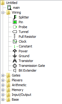
You can find transistors, power, and ground tools under the "Wiring" menu on the left hand side of Logisim:
To place a component on a circuit, click on it, and then click on the area on the right. The placed transistor looks like this:
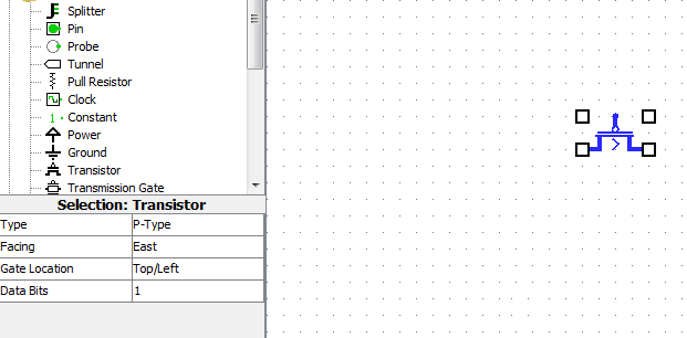
The transistor has three pins which are places wires can be connected. On the left is the "collector" which is usually connected to a power source. On the right is the "emitter" which is the output signal of the transistor. On top is the "base" which controls if the transistor is on or off.
Components such as transistors have various attributes that can be changed on the left. Transistors can be switched from p-type to n-type, and rotated.
Logisim also has components which will allow us to interact with our design. In the "Input/Output" section, you will find Buttons and LEDs:
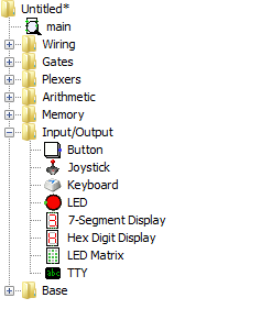
LEDS have one input pin which indicates if the LED will be lit or not. Buttons have one output pin which indicate if the button is currently pressed or not.
Logisim is somewhat more abstract than building a real circuit. For a switch to produce a current, it would have to be connected to a voltage source. Logisim buttons have a hidden voltage all ready to go. Likewise, the LEDS would have to be grounded to light.
With all of the power/ground wires a large circuit would need it would get quite messy!
In order to connect two components, they must be wired together. Use the Wiring Tool under the "Base" menu:
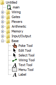
Click on the starting pin, and then click on the ending pin. This will draw a wire between them. You will often want to make several smaller wire segments to rout wires around other components.
In Code, Petzold designs a circuit to decide if a cat is acceptable according to a logical expression. This is used to illustrate the link between logic and circuits. His circuit is given below:
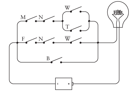
Below is a Logisim version of the same circuit:
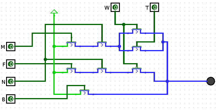
This circuit uses transistors controlled by pins instead of switches which would need to be opened and closed manually. A pin is an input or output of a circuit. Whether the cat is male or female is external to the circuit, so is controlled by a pin.
When the value of (M & N & (W | T)) | (F & N & ~W) | B is true, then the LED will light up. Notice that the ~W is handled with a P-type transistor which closes when a 0 is coming in. The other transistors are all N-type which close on a 1.
You can download this circuit here.
For this lab, you'll build a circuit along similar lines which will compute who wins a game of rock, paper, scissors. In this game, two players throw hand signals representing rock, paper, and scissors. The moves are compared and a winner is decided according to the following rules:
Your circuit should determine a winner based on the moves of each player.
You should build the circuit out of the following components:
Pins
You should use 6 pins (found under the wiring menu). Three pins are for player 1, and three are for player 2. Each player has a rock, paper, and scissors pin.
You should change them from three-state pins to two-state pins in the properties menu. Three-state pins can also be "turned off" where they do not represent a 0 or a 1, but that's not needed for this circuit.
You should also label each pin, so it's clear what it does!
Transistors
For each switch, you'll need a transistor connected to the appropriate pin. Be sure to select the right type between P-type and N-type.
Power
Each transistor needs a power source on the collector (left side). Whether they each have one, or share one doesn't matter.
LEDs
You should have two LEDs: one which represents player 1 winning, and another which represents player 2 winning. A tie game would be indicated with both LEDs off. Under no conditions should both LEDs be on!
Be sure to test that your circuit lights the appropriate LEDs for each possibility. You should test the case where the players throw the same moves (resulting in a tie), and when no move is thrown.
You don't need to test the case where multiple throws are selected (e.g. if the pins for player 1 throwing rock and paper are both on).
When your circuit works, please submit the .circ file under the lab assignment on Canvas
Copyright © 2024 Ian Finlayson | Licensed under a Attribution-NonCommercial 4.0 International License.