The Link Layer
Overview
As we've seen the lowest layer of a network, the physical layer, is concerned with sending binary data across some medium. The medium could be a wire or a wireless broadcast. The next layer above this is the link layer.
In the link layer we are still only concerned about sending data locally, but the link layer adds several services on top. In general, the physical layer is concerned with sending data over a direct connection, while the link layer is concerned with sending the data correctly.
We will talk about several aspects of the link layer, and use the terminology of nodes and links. Nodes include computers, servers, routers, switches and WiFi access points. The individual connections are the links.
There is not just one link layer protocol, there are several for different sorts of media. For user computers and servers, the link layer is normally implemented in the network interface controller.
For example, imagine an analogy where you are sick of the cold weather and decide to spend a week in Miami. Your trip might be broken into several steps:
- You drive your car to the Fredericksburg train station.
- You catch a train to the DC airport.
- You take a plane to the Miami airport.
- You call an Uber to take you to your hotel.
Here your house, the train station, the two airports, and the hotel are all nodes. The connections between them that you travel along are the links.
Link Layer Services
The link layer broadly provides the following 3 things on top of the physical layer:
- Framing
- Multiple access
- Error detection
We'll talk about each of these.
Framing
The physical layer sends bits across some medium without really breaking them up in anyway. The link layer breaks them into groups called "frames". The reason it does this is because it makes it easier to provide error detection.
If we just have an unending stream of bits, there's no real way to verify that any of them are sent correctly. When they are broken into frames, we can verify that each particular frame was sent without error.
Below is a diagram of how Ethernet frames are made. Ethernet is the most widely used link layer protocol for wired connections.
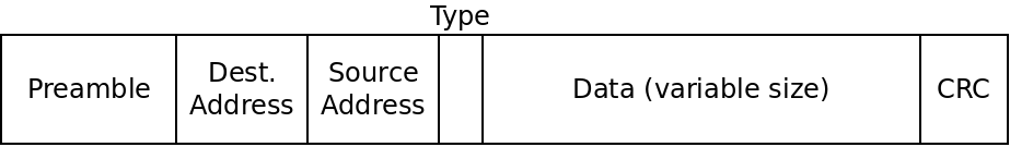
An Ethernet frame
The different fields are described below:
- The preamble is 8 bytes, and is always the same. The first 7 bytes are the
value
10101010. The purpose of these is to acclimate the receiver with the speed of the transmission. The last byte has the value10101011which signals the end of the preamble so the receiver knows the rest is the real data. - The destination address is a 6-byte MAC address. A MAC address is only relevant at the local level. So a router will use a MAC address to distinguish between 2 laptops connected to it. Each node in a local network has a MAC address.
- The source address is the 6-byte MAC address of the sender of the frame.
- The type is a 2-byte field which can be used to support multiple types of networks on the same hardware. Rarely used in practice.
- The data field can range from 46 bytes to 1500 bytes and contains the actual data being transmitted.
- The 4-byte CRC field is used for error detection as we will discuss.
Ethernet does not include the frame size in the frames. Instead it uses special begin/end symbols between frames so the receiver knows when the frame has been sent.
Multiple Access
While the link layer only deals with direct connections between two nodes in a network, we can't assume that there is only one sender and one receiver using a particular link.
For instance, several parties may be communicating with a wireless router at one time. Even an Ethernet cable may be sending frames between multiple parties at once.
Only a medium can't actually transmit multiple frames at once. This is called a collision and the data gets mixed up in an unintelligible way.
Thus the link layer needs to deal with how to allow access to multiple parties at different times in some way. This is called the "multiple access problem" and protocols meant to solve it are multiple access protocols.
There are three main sorts of multiple access protocols:
Channel Partitioning
Here we divide the channel up and give each party some part of the channel. There are two major ways channels can be divided: by time or by frequency. When dividing by time, each node in the network gets some amount of time with the channel all to itself.
With frequency division, we divide the bandwidth of a channel into multiple frequencies and assign them to each node.
Random Access
In this scheme, nodes transmit frames whenever they want to. When a collision inevitably occurs, it waits for a little while and then tries again. The trick is that each node uses random delays before trying again. In this way, odds are, one node will wait a shorter time and be able to transmit before a collision occurs.
An enhanced version of this called "exponential backoff" is commonly used. In this scheme we use random delays, starting with very short ones. But each time a consecutive collision occurs, we wait roughly twice as long as the last time. This way senders will avoid too many collisions without waiting longer than needed.
Taking Turns
In this approach, the nodes take turns somehow to share the channel. Unlike the time-based channel partitioning scheme, it is not pre-arranged. Instead, the nodes only use the channel if they actually need it. There are two approaches to taking turns protocols: polling and token-passing.
In a polling protocol, one node is designated the "coordinator" and it must poll the other nodes to see if they have data to send. If so, they are given some amount of time on the channel. If not, they are skipped. Bluetooth uses polling this way.
In token-passing, there is some predefined "token" frame which is sent amongst nodes in a fixed order. When a node is done transmitting, it sends the token to the next node. If that node needs to transmit, it does, so and then sends the token on. If not, it sends the token right away.
What are the advantages and disadvantages of these approaches?
Error Detection and Correction
No transmission line has 100% success rate. Interference can cause wires to send incorrect data, and wireless transmissions are even more vulnerable to this.
One important job of the link layer is to allow the receiver to sometimes (but not always) detect when a message has gotten scrambled. It's impossible to detect all potential errors, but we can control how unlikely an undetected error is.
The simplest error checking scheme we could have is a parity check. Say we want to send the following bytes to a receiver:
01001101
01100001
01110100
01101000
What we will do is count the number of 1's in each byte. Then we send an extra bit along with each byte. If the number of 1's was even, we make this extra bit a 0. If it was odd, we make it a 1.
This way, in each set of 9 bits there should be an even number of 1's. If there is not, something must have gone wrong. In the example above, we would send the following:
010011010
011000011
011101000
011010001
Of course, there are many errors that won't be caught with this scheme! In practice, more complex error detection schemes are used.
CRC
The error-checking scheme used by Ethernet is the Cyclic Redundancy Check (CRC). This is a more robust extension of the simple parity idea.
The math behind CRC is based on the exclusive or (XOR) operation. This binary operator takes two bit parameters and determines if exactly one of them is a 1:
| $A$ | $B$ | $A \oplus B$ |
|---|---|---|
| 0 | 0 | 0 |
| 0 | 1 | 1 |
| 1 | 0 | 1 |
| 1 | 1 | 0 |
XOR is depicted as the $\oplus$ symbol.
XOR can be seen as binary addition, except you throw away any carry.
XOR can also be seen as binary subtraction, except that in cases where you would need to borrow from the next column (the 0 - 1 case), you ignore the borrow and carry on as if you had.
Doing math this way is called "modular arithmetic" and is used in many cryptographic applications. When we talk about addition and subtraction in CRC, we actually mean that they should be done with XOR. Multiplication and division work the normal way, except that the adding and subtracting involve also is done modulo-2 (which means using XOR).
In CRC, the sender and the receiver must agree on a binary value called a generator, $G$. Ethernet uses 32-bit CRC which has a fixed generator of 33 bits. The value is 0x04C11DB7 in hex if you're curious.
If the sender wants to send $d$ bits to a receiver, then we actually send an additional $r$ bits such that the binary number formed by joining all the bits together is exactly divisible by $G$ with no remainder.
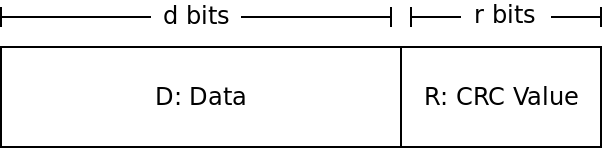
The goal of the sender is to find the value $R$ to make it so $DR$ is a multiple of whatever our $G$ is. The receiver will then check if the value $DR$ it receives is divisible by $G$.
So the big question is how can the sender find $R$?
If we view $DR$ as one binary number, then it can be seen as shifting $D$ to the left $r$ places, and then adding in $R$. But shifting a binary number to the left is just multiplying it by 2 (same as shifting a decimal number to the left is multiplying it by 10). So that gives us:
$DR = D \times 2^r \oplus R$
The $D$ part is shifted over $r$ places, which is the same as multiplying by $2^r$. Then, we just add in $R$ - but recall that we will use XOR instead of normal addition.
Because we want this value $DR$ to be divisible by our generator $G$, we want to find some value $n$ that we can multiply by $DR$ to get $G$. This gives us:
$D \times 2^r \oplus R = n \times G$
Now we can do some algebra to try and solve for $R$. If we XOR both sides by $R$, we get (XOR by the same value cancels itself out):
$D \times 2^r = n \times G \oplus R$
This tells us that if we divide $D \times 2^r$ by $G$ (or any multiple of $G$), then the remainder will be $R$ (because $R$ is the value added in afterwards). That means $R$ is the remainder we get if we divide $D \times 2^r$ by $G$:
$R = $ remainder of $\frac{D \times 2^r}{G}$
CRC Example
As an example, say we are doing 3-bit CRC with the following values:
$D = 101110$
$d = 6$
$G = 1001$
$r = 3$
$R = ?$
To solve this, we take the value $101110$ and multiply by $2^3$. This is the same as shifting it over three to the left giving us $101110000$. We then divide this value by our value of $G$, $1001$. The remainder is $R$.
What is the value? Remember to do XOR in place of subtraction!
CRC Effectiveness
CRC can detect all errors of length $r$ or less. With the widely used 32-bit CRC which is used by Ethernet, this means errors of 32 bits or fewer will be detected.
CRC also is extremely likely to catch errors past that point. The chance of catching an error with more than $r$ bits is $1 - 0.5^r$ With 32 bits, the chance of catching the error is 99.99999997671694%
It is more likely you will be struck by lightning today than have CRC-32 miss an error.
Conclusion
The link layer provides several important features on top of the physical layer. Principally it breaks a transmission into discrete frames, allows multiple parties to share a communication media, and provides error detection.
The next layer above is the network layer. This layer provides routing amongst several different nodes.