Introduction to Networks
Overview
Computer networks, and the Internet specifically, are a huge part of modern life. In this part of the course we will study how networks work internally. This is important for those working in software in any capacity, but especially system administrators as configuring networks in a secure way is necessary for nearly all systems.
In network terms, a node is any device capable of sharing data. These include computers, but also switches, routers, and other devices. A network is simply any group of at least two nodes that are connected together. The Internet is an inter-connected set of networks which spans the world.
While there are many ways that networks could be designed, any many ways that they have been designed in the past, we will look specifically at the Internet. These days, even when creating a private network, the underlying technology is almost always the same as is used in the Internet.
The world wide web is one particular application run on the Internet, involving web servers and web browsers. Some people use these topics inter-changeably, but they are distinct.
The Internet
The Internet is not owned by any one organization, but pieces of it are owned by different Internet Service Providers (ISPs). There are a number of organizations which govern the Internet:
- Internet Corporation for Assigned Names and Numbers (ICANN), which controls the allocation of IP addresses, domain names, and protocol port numbers.
- Internet Society (ISOC), which is the umbrella organization for the technical development of Internet protocols.
- Internet Governance Forum (IGF), which was created by the UN in 2006 and is the home for non-technical policy discussions.
The technical aspects of the Internet are developed through Requests for Comment (RFCs), which include protocol standards, proposed changes, and informational bulletins. The core protocols which underlie the Internet are published as RFCs:
- IP (RFC 791)
- ICMP (RFC 729)
- ARP (RFC 826)
- UDP (RFC 768)
- TCP (RFC 793)
Protocols
A protocol is the set of rules governing an interaction between two or more parties. Protocols exist between people. For instance, in most classrooms there is a protocol when a student has a question, something like the following:
- The student with a question raises their hand.
- The instructor calls on the student, inviting them to ask the question.
- The student asks their question.
- The instructor then answers the question back to the student.
If one party doesn't follow the protocol, then communication breaks down. For example, if the student yells out questions while the instructor is speaking, or if the instructor never calls on students, it won't work properly. The Internet is built on a number of protocols. The difference with computer protocols is that computers must be precise and rigorous.
An example protocol is HTTP, the Hypertext Transfer Protocol which describes the communication between web browsers and web servers when dealing with web content. HTTP defines many operations, the most common is the GET operation, which would proceed as follows:
- The browser sends the text "GET" followed by the name of the file they wish to receive.
- The server sends the text "HTTP/1.0" followed by a status code, such as 200 for success, 404 for file not found, 403 for forbidden, etc.
- The server sends various metadata about the file, such as the character encoding, and date.
- The server sends the file contents.
The Layered Model
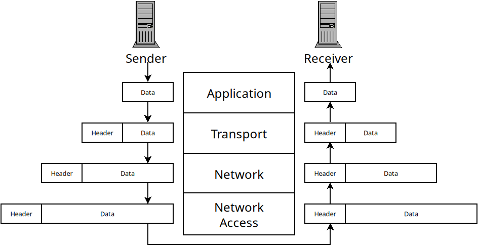
The Internet is not designed as a monolith, but is rather broken into layers, where each layer handles one specific aspect of communication and relies on the other layers for others. There are multiple network layer models. One is the OSI model:
| Layer | Purpose | |
|---|---|---|
| 7 | Application | Application-specific protocols |
| 6 | Presentation | Handles formatting of data for applications |
| 5 | Session | Manages communication sessions (i.e. identifying clients) |
| 4 | Transport | Manages reliable communication (i.e. missing or out-of-order data) |
| 3 | Network | Manages communication between nodes which are not directly connected |
| 2 | Data Link | Manages communication between two directly connected nodes |
| 1 | Physical | The actual physical communication media (i.e. WiFi or Ethernet) |
While the OSI model is widely referenced in texts, the TCP/IP model is more widely used in practice. It essentially collapses layers 5-7 into one application layer, and also layers 1-2 into one layer:
| Layer | Purpose |
|---|---|
| Application | Application-specific protocols |
| Transport | Manages reliable communication (i.e. missing or out-of-order data) |
| Network | Manages communication between nodes which are not directly connected |
| Network Access | Manages communication between two directly connected nodes |
Applications may or may not contain their own protocols for presentation of data or session management. The Network Access layer contains protocols for dealing with communication across physical media between two directly connected nodes.
When information is sent across a network from one host to another, it goes down the layers on the sender. Each layer adds header information and then passes it down to the layer below. Then, on the receiver side, it goes up the same layers. Each one handles the header information and removes it before passing the data to the layer above.
The Network Access Layer
This layer is responsible for sending data between two nodes which are directly connected. For instance, when you login to a WiFi network, you are only sending data directly between your computer and the wireless access point. This layer deals with issues that come up when doing this:
- Framing: breaking a stream of data into distinct chunks (which are called frames in this layer).
- Multiple Access: allowing multiple users to communicate over one transmission media. For instance, multiple users might be sending data to one router at a time (or even multiple applications on one machine).
- Errors: if data is corrupted during transmission we would like to know.
This layer is implemented in nodes in different ways. On computers, it is handled as part of the Operating System's networking modules. The physical device for network access is called a switch. Switches allow multiple nodes to connect to them and allow data to be sent from one node, to the switch, and then to another node.
It's a little complicated because most routers also function as switches, so they handle the Network Access layer, as well as Network Layer functions (in addition DHCP, DNS and other services).
The Network Access layer uses MAC addresses to identify
nodes. A MAC (media access control) address is 48-bits and uniquely assigned
to your network interface by the manufacturer. Switches use them to know
which node to forward data on to. We can see our MAC address with the
ip a command:
ifinlay@ilos:~$ ip a
1: lo: <LOOPBACK,UP,LOWER_UP> mtu 65536 qdisc noqueue state UNKNOWN group default qlen 1000
    link/loopback 00:00:00:00:00:00 brd 00:00:00:00:00:00
    inet 127.0.0.1/8 scope host lo
       valid_lft forever preferred_lft forever
    inet6 ::1/128 scope host noprefixroute
       valid_lft forever preferred_lft forever
2: wlp0s20f3: <BROADCAST,MULTICAST,UP,LOWER_UP> mtu 1500 qdisc noqueue state UP group default qlen 1000
    link/ether ec:63:d7:72:9b:65 brd ff:ff:ff:ff:ff:ff
    inet 172.16.31.71/24 brd 172.16.31.255 scope global dynamic noprefixroute wlp0s20f3
       valid_lft 596706sec preferred_lft 596706sec
    inet6 fe80::244f:d72a:8738:118a/64 scope link noprefixroute
       valid_lft forever preferred_lft forever
This shows our two network interfaces. All Linux machines provide a loopback interface which allows applications on the same machine to communicate with each other. That's the "lo" interface which is listed first. This machine also has a wireless card which is the second interface. Most consumer machines have only one network card, but servers often have multiple.
The MAC address is the "link/ether" address which on this machine is
ec:63:d7:72:9b:65. The IP address is also present in this output,
but we will talk about them next class.
Framing
One of the main jobs of the Network Access layer is to break data up into discrete chunks which are called "frames" (they are called other things in other layers). The reason for breaking them into frames is to provide error detection and correction.
If we just have an unending stream of bits, there's no real way to verify that any of them are sent correctly. When they are broken into frames, we can verify that each particular frame was sent without error.
Below is a diagram of how Ethernet frames are made. Ethernet is the most widely used protocol for wired connections.
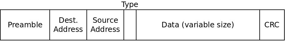
An Ethernet frame
The different fields are described below:
- The preamble is 8 bytes, and is always the same. The first 7 bytes are the
value
10101010. The purpose of these is to acclimate the receiver with the speed of the transmission. The last byte has the value10101011which signals the end of the preamble so the receiver knows the rest is the real data. - The destination address is the 6-byte MAC address of the node this frame is intended for.
- The source address is the 6-byte MAC address of the sender of the frame.
- The type is a 2-byte field which can be used to support multiple types of networks on the same hardware. Rarely used in practice.
- The data field can range from 46 bytes to 1500 bytes and contains the actual data being transmitted.
- The 4-byte CRC field is used for error detection as we will discuss.
Ethernet does not include the frame size in the frames. Instead it uses special begin/end symbols between frames so the receiver knows when the frame has been sent.
Multiple Access
While the link layer only deals with direct connections between two nodes in a network, we can't assume that there is only one sender and one receiver using a particular link.
For instance, several parties may be communicating with a wireless router at one time. Even an Ethernet cable may be sending frames between multiple parties at once.
Only a medium can't actually transmit multiple frames at once. This is called a collision and the data gets mixed up in an unintelligible way.
Thus the link layer needs to deal with how to allow access to multiple parties at different times in some way. This is called the "multiple access problem" and protocols meant to solve it are multiple access protocols.
There are three main sorts of multiple access protocols:
Channel Partitioning
Here we divide the channel up and give each party some part of the channel. There are two major ways channels can be divided: by time or by frequency. When dividing by time, each node in the network gets some amount of time with the channel all to itself.
With frequency division, we divide the bandwidth of a channel into multiple frequencies and assign them to each node.
Random Access
In this scheme, nodes transmit frames whenever they want to. When a collision inevitably occurs, it waits for a little while and then tries again. The trick is that each node uses random delays before trying again. In this way, odds are, one node will wait a shorter time and be able to transmit before a collision occurs.
An enhanced version of this called "exponential backoff" is commonly used. In this scheme we use random delays, starting with very short ones. But each time a consecutive collision occurs, we wait roughly twice as long as the last time. This way senders will avoid too many collisions without waiting longer than needed.
Taking Turns
In this approach, the nodes take turns somehow to share the channel. Unlike the time-based channel partitioning scheme, it is not pre-arranged. Instead, the nodes only use the channel if they actually need it. There are two approaches to taking turns protocols: polling and token-passing.
In a polling protocol, one node is designated the "coordinator" and it must poll the other nodes to see if they have data to send. If so, they are given some amount of time on the channel. If not, they are skipped. Bluetooth uses polling this way.
In token-passing, there is some predefined "token" frame which is sent amongst nodes in a fixed order. When a node is done transmitting, it sends the token to the next node. If that node needs to transmit, it does, so and then sends the token on. If not, it sends the token right away.
Error Detection and Correction
No transmission line has 100% success rate. Interference can cause wires to send incorrect data, and wireless transmissions are even more vulnerable to this. One important job of the link layer is to allow the receiver to detect when a message has gotten scrambled, as often as possible. It's impossible to detect all potential errors, but we can control how unlikely an undetected error is.
The simplest error checking scheme we could have is a parity check. Say we want to send the following bytes to a receiver:
01001101
01100001
01110100
01101000
What we will do is count the number of 1's in each byte. Then we send an extra bit along with each byte. If the number of 1's was even, we make this extra bit a 0. If it was odd, we make it a 1. This way, in each set of 9 bits there should be an even number of 1's. If there is not, something must have gone wrong. In the example above, we would send the following:
010011010
011000011
011101000
011010001
Of course, there are many errors that won't be caught with this scheme! In practice, more complex error detection schemes are used.
CRC
The error-checking scheme used by Ethernet is the Cyclic Redundancy Check (CRC). This is a more robust extension of the simple parity idea. The math behind CRC is based on the exclusive or (XOR) operation. This binary operator takes two bit parameters and determines if exactly one of them is a 1:
| $A$ | $B$ | $A \oplus B$ |
|---|---|---|
| 0 | 0 | 0 |
| 0 | 1 | 1 |
| 1 | 0 | 1 |
| 1 | 1 | 0 |
XOR is depicted as the $\oplus$ symbol. XOR can be seen as binary addition, except you throw away any carry. XOR can also be seen as binary subtraction, except that in cases where you would need to borrow from the next column (the 0 - 1 case), you ignore the borrow and carry on as if you had.
Doing math this way is called "modular arithmetic" and is used in many cryptographic applications. When we talk about addition and subtraction in CRC, we actually mean that they should be done with XOR. Multiplication and division work the normal way, except that the adding and subtracting involved also is done modulo-2 (which means using XOR).
In CRC, the sender and the receiver must agree on a binary value called a
generator, $G$. Ethernet uses 32-bit CRC which has a fixed generator
of 33 bits. The value is 0x04C11DB7 in hexadecimal and 79764919 in decimal. If
the sender wants to send $d$ bits to a receiver, then we actually send an
additional $r$ bits such that the binary number formed by joining all the bits
together is exactly divisible by $G$ with no remainder.
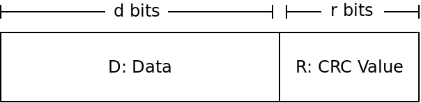
The goal of the sender is to find the value $R$ to make it so $DR$ is a multiple of whatever our $G$ is. The receiver will then check if the value $DR$ it receives is divisible by $G$. If so, no error has occurred, if it is not divisible by $G$, then an error must be present.
So the big question is how can the sender find $R$?
If we view $DR$ as one binary number, then it can be seen as shifting $D$ to the left $r$ places, and then adding in $R$. But shifting a binary number to the left is just multiplying it by 2 (same as shifting a decimal number to the left is multiplying it by 10). So that gives us:
$DR = D \times 2^r \oplus R$
The $D$ part is shifted over $r$ places, which is the same as multiplying by $2^r$. Then, we just add in $R$ - but recall that we will use XOR instead of normal addition.
Because we want this value $DR$ to be divisible by our generator $G$, we want to find some value $n$ that we can multiply by $DR$ to get $G$. This gives us:
$D \times 2^r \oplus R = n \times G$
Now we can do some algebra to try and solve for $R$. If we XOR both sides by $R$, we get (XOR by the same value cancels itself out):
$D \times 2^r = n \times G \oplus R$
This tells us that if we divide $D \times 2^r$ by $G$ (or any multiple of $G$), then the remainder will be $R$ (because $R$ is the value added in afterwards). That means $R$ is the remainder we get if we divide $D \times 2^r$ by $G$:
$R = $ remainder of $\frac{D \times 2^r}{G}$
CRC Example
As an example, say we are doing 3-bit CRC with the following values:
$D = 101110$
$d = 6$
$G = 1001$
$r = 3$
$R = ?$
To solve this, we take the value $101110$ and multiply by $2^3$. This is the same as shifting it over three to the left giving us $101110000$. We then divide this value by our value of $G$, $1001$. The remainder is $R$.
What is the value? Remember to do XOR in place of subtraction!
CRC Effectiveness
CRC-32 guarantees:
- All single-bit errors are detected.
- All double-bit errors are detected.
- All burst errors up to 32-bits are detected. A "burst error" is a set of sequential bits which may or may not be flipped.
- Other errors are very likely detected. The chance of another sort of error being missed is $1/2^{32}$, or one in about 4 billion.
So CRC is extremely effective. You are about 10 times more likely to be struck by lightning today than have CRC miss a random error in a transmission.
The Layers Above
The Network Access layer allows us to reliably communicate between two nodes that are directly connected. Over the next several classes, we will look at how the other layers allow us to:
- communicate between nodes which are not directly connected (Network)
- deal with data that never arrives or arrives out of order (Transport)
- implement different applications such as HTTP, DNS, SSH, etc (Application)