Flip Flops and Registers
Overview
In this lab we will work on building sequential circuits. We will start by implementing the flip flop from class, then build a register which can store multi-bit values. We will then combine the register with an adder to create a small circuit that increments a value every clock cycle.
1 - Build a Flip Flop
Start by clicking on "Project-Add Circuit" to create a circuit for an edge-triggerred D-Type flip flop with reset following this design:
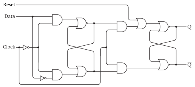
Make Reset, Data and Clock input pins, and $Q$ and $\overline{Q}$ output pins. Logisim includes a built-in component for an edge-triggered D-Type flip flop. After this lab, you can use that, but we will build our own first!
Also note that the combinational analysis tool does not work for building sequential circuits!
2 - Build a Register
Now we will build a register which can store multiple bits and allow us to read or write them as a single value. To do this, add a new circuit with the "Project-Add Circuit" menu option.
Then put eight of your flip flops into the register. Create input pins for the clock and reset, and connect them to all of the flip flops. By using the same clock signal, the flip flops will stay synchronized. We can also clear all the flip-flops at once.
Next we will need an input pin for the value to be stored in the register. After creating the input pin, change the "Data Bits" from 1 to 8. In order to store the 8-bit value, we need to direct each bit to the 8 flip flops data inputs. This can be done with a "Splitter" under the "Wiring" menu.
In order to be able to read the 8-bit value stored, we need an 8-bit output pin as well. To route the 8 $Q$ values from the flip flops to another splitter which is connected to the output pin.
You can test your register by putting a value into the input pin, and then setting the clock to 1. At this point, the value should appear on the output pin. Now, you can change the input without affecting the output (because of the edge triggering). Verify that the input is only applied when the clock switches to 1, and that the reset pin sets the value to 0.
3 - Build a Counter
Now we will build a counter out of a register and an adder. In the main part of your circuit, place one of the registers you've created.
Create a Clock which can be found under the Wiring menu. Logisim has the ability to cycle this clock automatically. Connect it to the clock pin on your register.
Create a pin for the reset signal and connect it to the register as well.
Next place an 8-bit output pin and connect it to the output of the register. This way, we will be able to see the current register value.
Now place an adder from the Arithmetic menu. The adder will add the value 1 to the register every clock cycle. One input to the adder should be the current value of the register, and the other should be the constant value 1. Constants are under the Wiring menu.
The output of the adder will then connect to the input of the register. Notice that this circuit also utilizes feedback. The value of the register cycles back to an input of the adder and the output goes into the register.
Testing
To test your circuit, start by turning on the reset signal to set the value to 0.
Now, when you change the clock from 0 to 1, the value of the circuit should increment. When the clock changes from 1 to 0, nothing should happen. This is because the flip flop is built to switch on the rising edge of the clock.
We can also have Logisim toggle the clock automatically. You can turn this on by selecting "Ticks Enabled" from the Simulate menu. You can also change the clock frequency from 0.25 HZ (1 change every 4 seconds) to 4.1 KHZ (4.1 thousand changes every second).
Make sure your circuit increments the register value on every rising edge. The circuit will wrap around when it gets to the "11111111" value.
Submitting
When your circuit works, please submit the .circ file under the lab assignment on Canvas